Basic Data Structure Representing a Mesh
Contents
Data structure: node and elem
Two matrices node(1:N,1:d) and elem(1:NT,1:d+1) are used to represent a d-dimensional triangulation embedded in  , where N is the number of vertices and NT is the number of elements.
node(k,1) and node(k,2) are the x- and y-coordinates of the k-th node for points in 2-D. In 3-D, node(k,3) gives the additional z-coordinates of the k-th node.
elem(t,1:3) are indices of 3 vertices of triangle t. elem(t,1:4) are indices of 4 vertices of tetrahedron t. By convention, the vertices are ordered such that the signed area/volume is positive. Therefore in 2-D, three vertices of a triangle is ordered counterclockwise and in 3-D, the four vertices of a tetrahedron follows the right-hand rule.
Example: L-shape domain in 2-D
node = [1,0; 1,1; 0,1; -1,1; -1,0; -1,-1; 0,-1; 0,0];  % coordinates
elem = [1,2,8; 3,8,2; 8,3,5; 4,5,3; 7,8,6; 5,6,8];     % connectivity
showmesh(node,elem);
axis on
findnode(node);       % plot indices of all vertices
findelem(node,elem);  % plot indices of all triangles

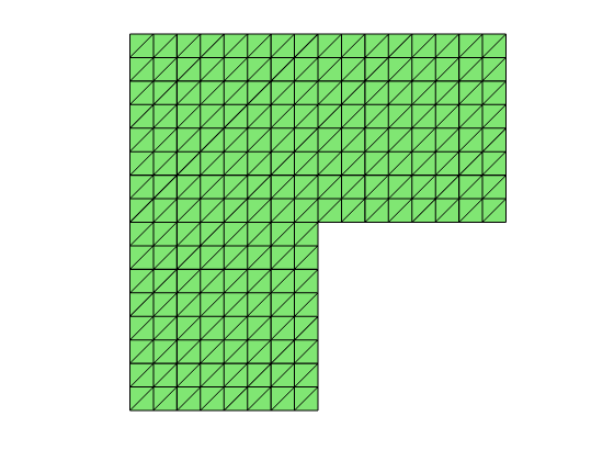
Apply uniform refinement to obtain a fine mesh.
for i = 1:3
    [node,elem] = uniformrefine(node,elem);
end
showmesh(node,elem)
Example: Cube in 3-D
node = [-1,-1,-1; 1,-1,-1; 1,1,-1; -1,1,-1; -1,-1,1; 1,-1,1; 1,1,1; -1,1,1];
elem = [1,2,3,7; 1,6,2,7; 1,5,6,7; 1,8,5,7; 1,4,8,7; 1,3,4,7];
clf; showmesh3(node,elem,[],'FaceAlpha',0.25);
view([-53,8]);
axis on
findnode3(node);
findelem3(node,elem);

Apply uniform refinement to obtain a fine mesh.
for i = 1:2
    [node,elem] = uniformrefine3(node,elem);
end
showmesh3(node,elem,[],'FaceAlpha',0.25); view([-24 10]);

Order of vertices: orientation
Any permutation of vertices of an element will represent the same abstract simplex. By convention, the vertices of a simplex is ordered such that the signed volume is positive. Therefore in 2-D, three vertices of a triangle is ordered counterclockwise and in 3-D, the ordering of vertices follows the right-hand rule. The function fixorientation will compute the signed area or volume and permute vertices if necessary.
node = [1,0; 1,1; 0,1];
elem = [1 3 2];
figure(4);
subplot(1,2,1)
showmesh(node,elem)
findnode(node,elem)
display('Clockwise'); display(elem)
elem = fixorientation(node,elem);
display('Counter-Clockwise'); display(elem)
Clockwise

elem =

     1     3     2

Counter-Clockwise

elem =

     1     2     3

Order of vertices: longest edge
An even permutation of vertices is still allowed to represent the same simplex with the same orientation.
- The function label will permute the vertices such that elem(t,2:3) is the longest edge of t.
- The function label3 will permute the vertices such that elem(t,1:2) is the longest edge of t.
These functions are important for bisection methods of triangulations.
node = [1,0; 1,1; 0,1];
elem = [1 2 3];
subplot(1,2,1)
showmesh(node,elem)
findnode(node,elem)
display('Before labeling'); display(elem)
elem = label(node,elem);
display('After labeling'); display(elem)
display('elem(t,2:3) is the longest edge')
Before labeling

elem =

     1     2     3

After labeling

elem =

     2     3     1

elem(t,2:3) is the longest edge

node = [-1,-1,-1; 1,-1,-1; 1,1,-1; -1,1,-1; -1,-1,1; 1,-1,1; 1,1,1; -1,1,1];
elem = [1,2,3,7; 1,6,2,7; 1,5,6,7];
figure;
showmesh3(node,elem,[],'FaceAlpha',0.25); view([-53,8]);
findnode3(node,[1 2 3 5 6 7]);
findelem3(node,elem);
display('Before labeling'); display(elem)
elem = label3(node,elem);
display('After labeling'); display(elem)
display('elem(t,1:2)=[1 7] is the longest edge')
Before labeling

elem =

     1     2     3     7
     1     6     2     7
     1     5     6     7

After labeling

elem =

     1     7     2     3
     1     7     6     2
     1     7     5     6

elem(t,1:2)=[1 7] is the longest edge
